The electronic gear ratio parameters for the DSY series drivers are defined in the parameter list as follows:

-
P04-07: Electronic Gear 1 Numerator
-
P04-09: Electronic Gear 1 Denominator
-
P04-11: Electronic Gear 2 Numerator
-
P04-13: Electronic Gear 2 Denominator
The transmission diagram for the electronic gear ratio is as follows:
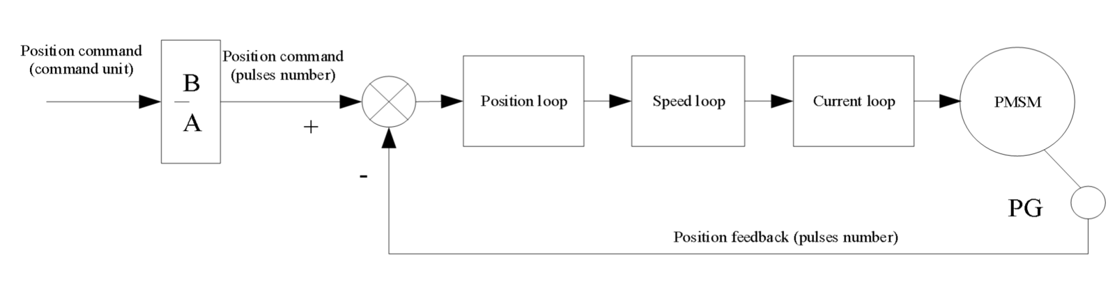
- When P04-05 = 0, the motor is connected to the load through a gear reducer. Assuming the reduction ratio between the motor shaft and the load shaft is n/m (the motor shaft rotates m turns while the load shaft rotates n turns), the electronic gear ratio is calculated as follows:

This driver model supports up to two sets of electronic gear ratios. The active gear ratio can be selected using the Electronic Gear Ratio Switch function (multi-function input terminal FunIN.23).
- When P04-05 ≠ 0:

In this case, both sets of electronic gear ratios and the electronic gear switch function are disabled.
- The valid setting range for the electronic gear ratio is:

If the ratio falls outside this range, fault Er.49 (Electronic Gear Ratio Setting Fault) will occur.