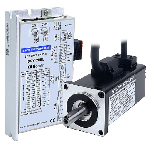
The DSY-RS series low-voltage DC servo drives support the standard Modbus RTU communication protocol, allowing a Modbus master to read from or write to single or multiple parameters.
The Modbus register address corresponding to an internal drive parameter is calculated using the following formula:
P(MmNn) = Mm × 256 + Nn
In this formula, Mm represents the parameter group number and Nn represents the parameter index within that group. The result is a decimal register address.
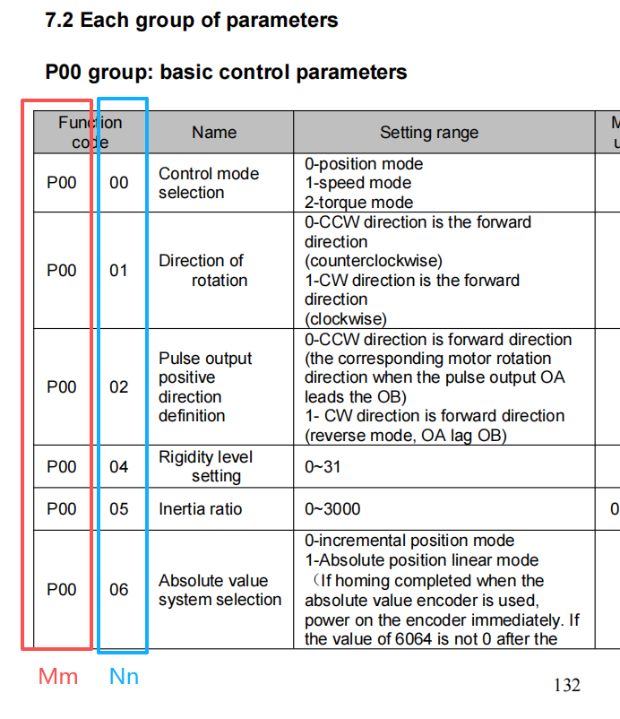
For example, using the P00 group parameters and the relationship between Mm and Nn shown in the figure above:
P0000 = 0 × 256 + 0 = 0 (decimal). The corresponding 16-bit address for 0 is 0000.
All register addresses for the 19 parameter groups (P00 through P18) in the DSY-RS series drive are calculated the same way. As another example, the address for parameter P1801 is:
P1801 = 18 × 256 + 1 = 4609 (decimal). Converting 4609 to hexadecimal gives 1201.
Important Note Regarding Addressing Offsets:
Some PLCs and HMIs use Register Address + 1 in their Modbus programming instead of the actual register address. This is because certain PLC and HMI vendors apply a 1-based addressing convention in their Modbus implementation, adding an offset of 1 to the standard 0-based Modbus register addresses.
Before configuring Modbus communication with the servo drive, verify whether your master device uses 0-based or 1-based addressing, and apply the appropriate offset to ensure correct parameter read/write operations.