1. Reading Servo Motor Encoder Position from a Host Controller
Servo motor encoders can relay position data to a host controller (upper computer) through digital input/output (DI/DO) circuits on the drive's rear control board.
When a PLC controls a servo or stepper system, encoder feedback is typically not required for position determination. The PLC sends position pulses to the servo drive via its instructions, and the drive's internal position loop handles position feedback.
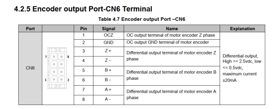
Most servo drives include a pulse division output function. If the host controller needs to receive encoder data independently, the motor's encoder pulses can be output in divided form, serving as a reference for the host system's closed-loop control.
For the T6 series, the pulse division output interface is CN6. The wiring diagram is shown below:
2. Reading Stepper Motor Encoder Position from a Host Controller
In a closed-loop stepper motor system, the host controller drives the motor by sending pulses to the driver. Pulse frequency controls speed, and pulse count controls position. Simultaneously, the driver transmits pulse count data back to the host controller to report the motor's actual position and speed.
To implement this type of control, the PLC must support bus communication—either RS-485 or EtherCAT. The driver must also support the corresponding bus protocol. This enables the host controller to retrieve position and speed data directly through bus messages.
Regarding stepper motor encoders: All stepper motors we sell use incremental encoders with multi-turn feedback. Some encoders include a Z-phase signal, while others do not. Encoders without a Z-phase signal lack a homing function, and absolute position cannot be determined. For encoders equipped with a Z-phase signal, a homing routine must be programmed in the host controller to enable position reading and homing.