When using A6 servo drives, you may notice two DC bus terminals located at the power terminals:
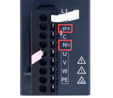
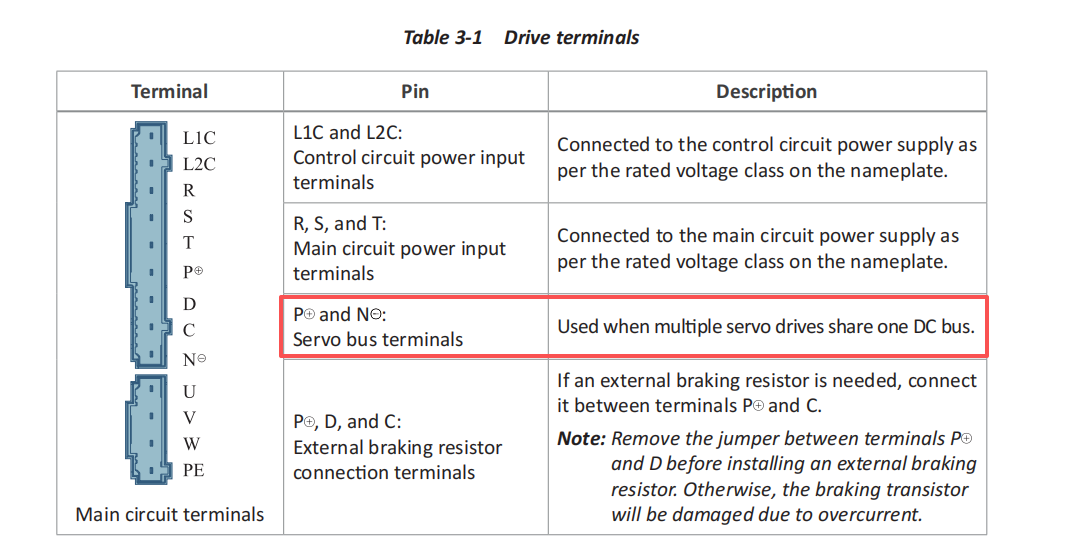
The primary purpose of a common DC bus is energy efficiency: servo drives operating in regenerative mode feed energy back into the DC bus. Because the combined bus capacitance is significantly increased, the rise in bus voltage caused by this feedback is greatly reduced, enabling energy recovery and reuse. Furthermore, as the overall bus voltage becomes more stable, the frequency of braking resistor discharge cycles is reduced, lowering energy consumption while also extending the service life of braking resistors.
When implementing a common DC bus with A6 drives, the AC input for each individual drive must still be connected. It is not permissible to use the input rectifier of a single drive to power multiple other servo drives. Connecting 220 V drives and 380 V drives to the same common DC bus is also not allowed.
Below are detailed instructions for different wiring configurations.
- Common DC Bus for Drives with Identical Power Ratings
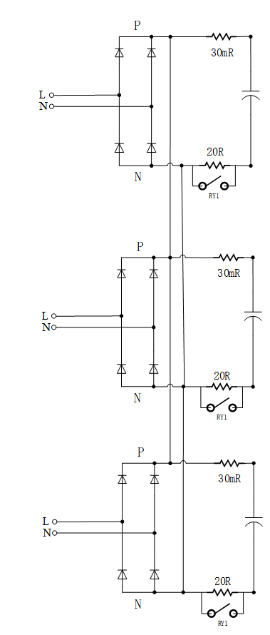
As illustrated, since the AC input (L/N) for each drive is already connected, simply connecting their DC bus terminals together is sufficient.
Points to Note:
- When a large number of drives share a common DC bus, the combined bus capacitance is substantial. If the regenerative energy from servo operation is relatively low, braking resistors may not be necessary (neither internal nor external resistors need to be used).
- If overvoltage alarms still occur after connecting the common DC bus, it indicates that the combined bus capacitance is insufficient to absorb the regenerative energy. In this case, braking resistors are required. You can enable the internal braking resistor on the servo drives that are triggering the overvoltage alarm. (Repeated overvoltage alarms may damage the bus capacitors.)
- If enabling the internal braking resistor on one servo drive leads to a braking resistor overload alarm, it means that single resistor's capacity is insufficient to handle the regenerative energy. You need to increase the number of drives with their internal braking resistors enabled. You can selectively enable the internal resistors on an appropriate number of drives, or enable this function on all connected servo drives.
- If you prefer not to use internal braking resistors (e.g., drives rated 400 W and below do not have built-in resistors), you can connect external braking resistors instead. If many drives share a common DC bus, it is recommended to connect one external braking resistor for every 3 or 4 drives. Select the resistance value based on the minimum recommended value in the manual. Since part of the regenerative energy is absorbed by the combined bus capacitance, the power rating of the external resistor can be chosen slightly lower (calculate based on the power rating recommended in the manual for a single drive's external resistor).
- Common DC Bus for Drives with Adjacent Power Ratings
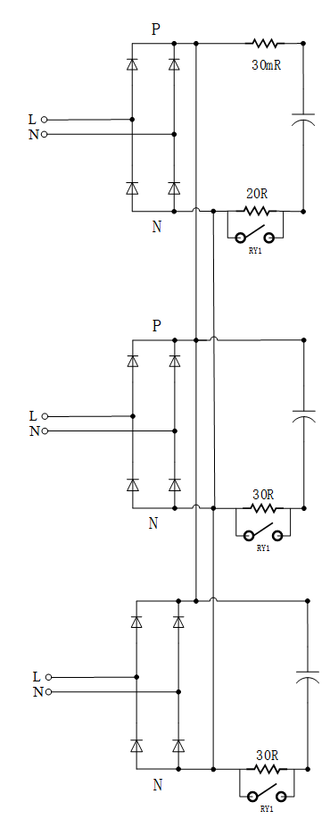
A specific scenario arises when connecting drives with adjacent power ratings: having multiple larger drives and one smaller drive on the same bus. For example, when power is applied, the input rectifier of the single smaller drive will charge not only its own DC bus capacitors but also those of the several larger drives. Consequently, the surge current (I_FSM) experienced by the smaller drive's input rectifier will be higher. However, because the power ratings are adjacent, key rectifier ratings—such as surge current capacity (I_FSM) and thermal stress tolerance (I²t)—as well as bus capacitance values, do not differ drastically. Engineering analysis indicates that component failure is unlikely under normal operating conditions in this scenario. Therefore, sharing a common DC bus across adjacent power ratings is permissible, provided all wiring guidelines are strictly followed.
Points to Note:
- The usage of internal braking resistors is similar to Point 2 mentioned above.
- When using external braking resistors, prioritize connecting them to the larger drives. Select the resistance value based on the minimum recommended value in the manual. Because the combined bus capacitance is larger, it can absorb more regenerative energy, allowing the power rating of the external braking resistor to be chosen slightly lower (calculate based on the power rating recommended in the manual for a single drive's external resistor).
Important Reminder: Under normal circumstances, we do not recommend implementing a common DC bus. Improper application or wiring errors can lead to drive damage. This procedure requires careful attention!