A DIN rail power supply is a switching power supply that converts an unregulated input voltage into a stable, regulated output voltage. Compared to linear power supplies, switching power supplies offer significantly higher conversion efficiency, lower weight, and a more compact design.
The defining feature of a DIN rail power supply is its mounting method, which gives it its name. The unit is mounted on a standardized DIN rail, also known as a top-hat rail.
DIN rails are metal mounting rails with fixed, standardized dimensions originally defined by the German Institute for Standardization (DIN). This mounting method has been adopted worldwide as a European (EN) and International (IEC) standard. It is suitable for most industrial applications and has become a standard component in electrical cabinets, distribution boxes, and machines. A virtually unlimited range of electrical components—power supplies, circuit breakers, relays, industrial PCs, and more—are available for DIN rail mounting.
The most common DIN rail size is 35 mm in width (often referred to as a 35 mm DIN rail or TS-35). Other sizes, such as 15 mm and 7.5 mm in height, are also used for smaller or specialized components.
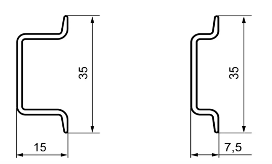
Cross-section of a 15 mm (height) DIN rail Cross-section of a 7.5 mm (height) DIN rail
There are two common configurations for powering stepper motor drivers:
Option 1: One power supply for multiple drivers
Advantages:
- Cost and space savings: Using a single power supply reduces both equipment cost and the space required, which is highly advantageous in applications with limited space and budget.
- Simplified wiring: A single power supply can power multiple drivers, simplifying the layout and management of power cables.
- Convenient maintenance: If a problem occurs, only one power supply needs to be maintained or replaced, rather than inspecting multiple power supply units.
Disadvantages:
- Power load: The power supply must provide enough current and voltage to support all connected drivers. If the power supply is not rated to deliver sufficient output for all drivers, it may become overloaded or experience voltage drops, affecting driver and motor performance.
- Electrical noise and interference: Sharing a power supply among multiple drivers can lead to noise coupling through the shared power bus. Electrical noise generated by one driver may affect the performance of others.
- Single point of failure: If the power supply fails, all drivers connected to it will be affected, potentially causing the entire system to shut down.
Option 2: One power supply per driver
Advantages:
- Independent power supply: Each driver has its own dedicated power supply and is not affected by the operation of other drivers. This improves overall system stability and reliability.
- Isolation of power and load: Each driver has its own power supply, which prevents overloading a shared supply and reduces the impact of power fluctuations on other devices.
Disadvantages:
- Increased cost: Each driver requires a separate power supply, which increases overall system cost.
- Space consumption: Each driver requires an additional power supply unit, requiring more installation space.
- Increased maintenance complexity: While a single power supply failure only affects one driver (others continue to operate normally), troubleshooting requires inspecting multiple power supply units to identify the faulty one, which can increase maintenance time and effort.
Power Supply Sizing Guidance
When using Option 1 (one power supply for multiple drivers), ensure the power supply can deliver sufficient current. A basic sizing formula is:
Total required current = Sum of all driver operating currents × Safety factor (typically 1.2 to 1.5)
For example, if three drivers each draw 3 A, the total required current is 3 × 3 × 1.3 = 11.7 A. Select a power supply rated for at least 12 A at the required output voltage.
Always refer to the specific driver's datasheet for its operating current requirements and voltage specifications.