Holding torque, also known as static torque, refers to the maximum torque a stepper motor can produce when it is energized but not rotating (i.e., in a stationary state).
Here is an intuitive way to understand it: when you supply the rated current to the stepper motor's windings (with the shaft locked), and then attempt to turn the motor shaft with a wrench, you must apply a certain amount of force to overcome the magnetic resistance and initiate rotation. The minimum torque required to start rotating the motor shaft is the holding torque.
Key Characteristics
- Static Metric: Holding torque is measured at zero speed and represents the motor's "locking" or "self-locking" capability when stationary.
- Maximum Torque Point: Holding torque is the theoretical maximum torque the stepper motor can deliver.
- Proportional to Current: The magnitude of the holding torque is directly related to the current flowing through the windings. The higher the applied current (without exceeding the maximum allowable current for the motor and driver), the greater the holding torque.
- Not the Running Torque: This distinction is crucial. Once the motor starts rotating, the actual torque it can output (referred to as "running torque") decreases significantly as speed increases and is always lower than the holding torque. This is primarily due to factors such as the inductance of the motor windings and the back EMF generated during rotation.
Engineering Significance of Holding Torque
- Core Basis for Motor Selection: Holding torque is one of the primary parameters used to select and compare different stepper motor models. It directly reflects the motor's torque capability. For example, when a heavy load must be moved in a linear-motion application, you first calculate the required torque and then select a motor whose holding torque exceeds that value.
- Maintaining Position: In applications where the motor must firmly hold its position while stationary (e.g., a 3D printer nozzle during a print pause, or a robotic arm after reaching a target position), a high holding torque ensures that the position does not shift under external forces.
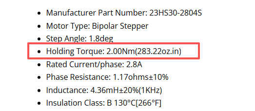
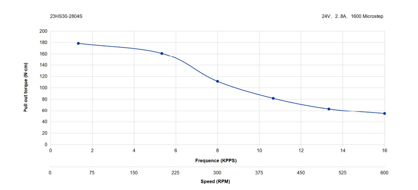
As shown in the diagram, the stepper motor model 23HS30-2804S has a static holding torque of 2 Nm. However, during actual operation, its dynamic torque decreases as speed increases. This is reflected in the speed–torque curve, where all maximum running torque values are lower than the static holding torque value.
I. Inductive Characteristics of the Windings
The stator windings of a stepper motor are significant inductive components. The fundamental characteristic of an inductor is to resist changes in current. Under static conditions, the windings carry a stable DC current, which is constant, so the inductance presents no opposition.
However, when the motor needs to rotate, the driver sends high-frequency pulsed voltage signals to the windings to switch the magnetic field rapidly. At this point, the inductance causes a critical issue: the current builds up much more slowly than the voltage changes.
- At low speeds: The pulse frequency is low, allowing relatively sufficient time for the current to rise to its rated value. As a result, the torque remains close to the holding torque.
- At medium to high speeds: The pulse frequency increases, and the duration of each pulse becomes extremely short. The current does not have enough time to reach its peak before the next pulse arrives. This causes the average current in the windings to decrease significantly.
Conclusion: Torque is proportional to current. Because inductance prevents the current from building up rapidly, the average current during rotation is lower than the static current. Consequently, the actual output torque is necessarily less than the holding torque.
II. Back EMF (Electromotive Force)
When a stepper motor rotates, it acts not only as a motor but also as a generator. The rotating permanent-magnet rotor cuts the magnetic field lines of the stator windings, generating—according to the law of electromagnetic induction—an induced electromotive force (EMF) that opposes the driving voltage. This is known as Back EMF.
- Effect: The back EMF counteracts a portion of the voltage supplied by the driver. According to Ohm's law, the effective voltage across the windings is reduced, making it harder to push current through them.
- Relationship with Speed: The magnitude of the back EMF is proportional to the rotational speed. The higher the speed, the greater the back EMF, the stronger its opposing effect on the current, and the more severe the torque drop.
Important Relationship: Back EMF is not an independent cause but an inevitable consequence of electromagnetic induction once the motor rotates. A motor with high inductance will typically also generate higher back EMF. Thus, inductance is the cause and back EMF is the effect; together, they cause the torque to drop as speed increases.
III. Other Losses
During high-speed operation, the magnetic field in the motor's core changes at a high frequency, generating eddy-current losses and hysteresis losses. This energy is dissipated as heat and cannot be converted into mechanical work, further reducing the motor's output efficiency and available torque.
Therefore, when selecting a stepper motor, you must never rely solely on the holding torque to evaluate its ability to drive a load during operation. You must refer to the torque–speed curve provided on our website. Ensure that the motor can still deliver torque greater than the load resistance at the maximum speed required by your application, and leave a sufficient safety margin (typically 30%–50%) to prevent lost steps.