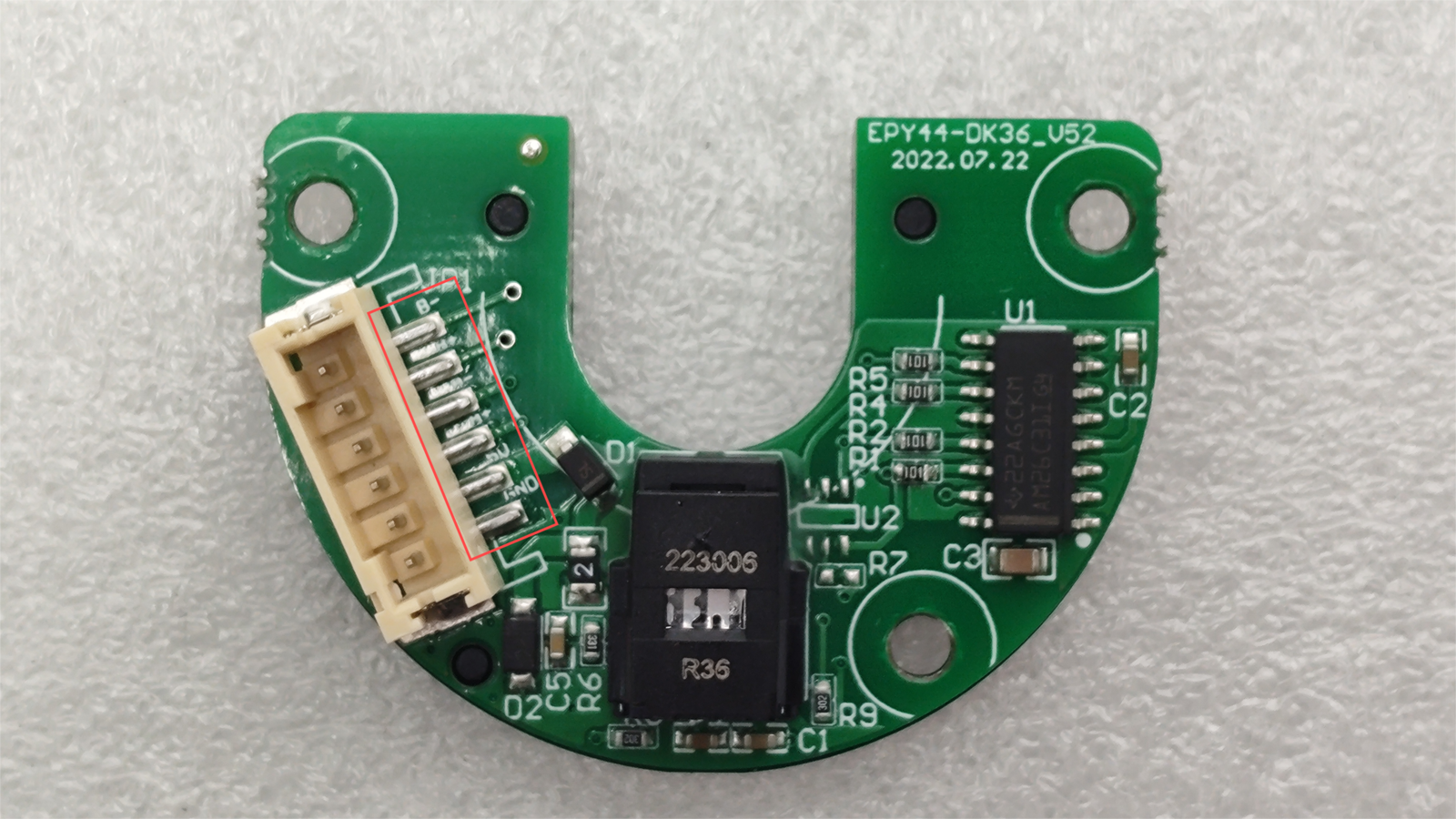
During the operation of a closed-loop stepper motor, if the encoder becomes damaged, the driver will issue a position deviation alarm. This article describes common causes of encoder damage and how to inspect the encoder.
Common Causes of Encoder Damage
- Fluctuation of Encoder Input Voltage and Current
The signal voltage range supported by our standard encoders is 5 V ± 0.5 V. If the voltage received by the encoder exceeds its maximum rated voltage, the encoder may be damaged.
- Unstable Signal Voltage Output from the Driver
Typically, internal components in the driver regulate the output signal voltage and limit fluctuations. However, if these components are damaged, the driver's output signal voltage may become unstable. If the output voltage exceeds the encoder's rated range, it may damage the encoder's ESD protection diode.
- Abnormal Encoder Cable or Connector
Possible issues include: broken wires at the connector, poor contact between mating connectors, cold solder joints between the connector and the PCB, or local short circuits. Any of these conditions may prevent the encoder from functioning properly.
- Environmental Damage to the Encoder
If the motor is used in an environment where static electricity is present, the encoder may be damaged by electrostatic discharge (ESD).
- Solder Joint Degradation in the Encoder
All motors undergo factory inspection before shipment, which minimizes the chance of encoder defects. However, prolonged exposure to high ambient temperatures during operation may cause solder joints on the encoder components to degrade or develop cold solder joints, leading to encoder failure.
Inspection Methods
- Check Whether the Encoder Sensor Is Connected
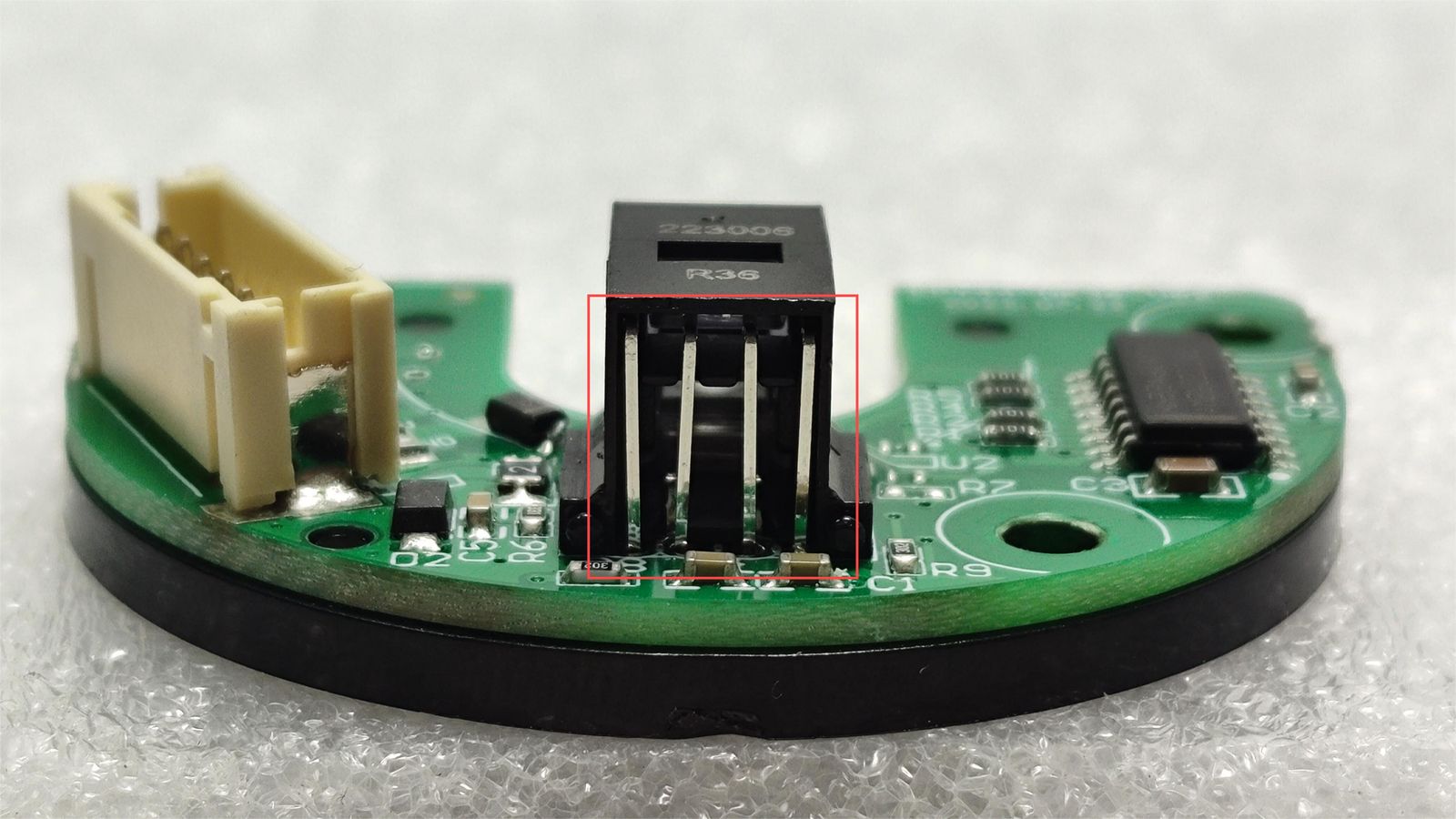
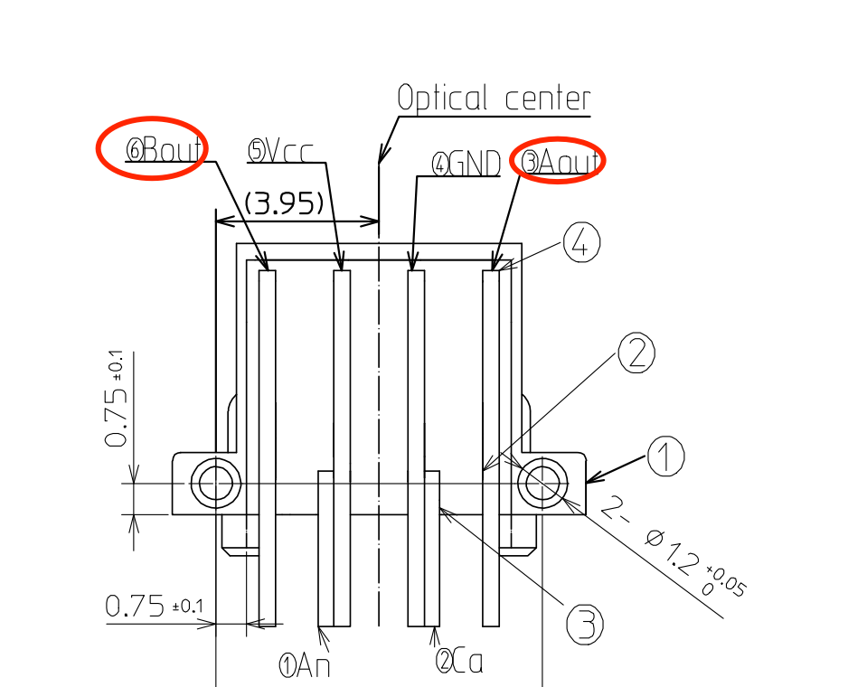
Measure the encoder pins as shown in the figure to test the A signal and B signal respectively.
- Check Whether the ESD Protection Diode Is Burned Out
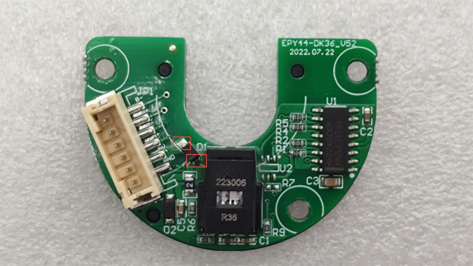
Visually inspect the diode for signs of burnout. Alternatively, use a multimeter to measure the diode's resistance: first, connect the multimeter's test probes to the positions marked in the figure and record the resistance reading; then, swap the probe positions and measure again. If one reading shows low resistance and the other shows high resistance (or open circuit), the diode is functioning normally. If both readings are near 0 Ω, the diode is shorted and damaged. If both readings show open circuit (infinite resistance), the diode is open and damaged.
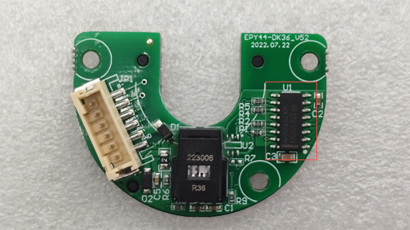
- Inspect the Differential Line Driver IC for Burnout
The IC marked in the image below is the differential line driver IC on the encoder board.
- Measure Continuity Between Connector Pins and Cable
A disconnected cable or cold solder joint at the pins can also manifest as an encoder failure. Use a multimeter to check for continuity between the PCB connector pins and the cable.