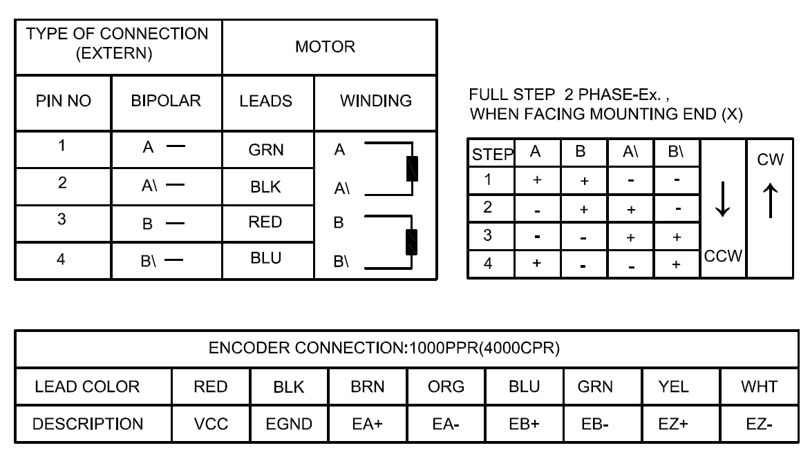
For STEPPERONLINE closed-loop stepper motors equipped with GX-16 and DB-15 connectors, the wiring sequence is as follows:
1. Motor Connection
Option A
| Pin | 1 | 2 | 3 | 4 |
|---|---|---|---|---|
| Pole | A+ | A- | B+ | B- |
| Color | White | Green | Blue | Black |
Option B
| Pin | 1 | 2 | 3 | 4 |
|---|---|---|---|---|
| Pole | A+ | A- | B+ | B- |
| Color | Black | Green | Red | Blue |
2. Encoder Connection
| Pin | 2 | 3 | 1 | 13 | 11 | 12 |
|---|---|---|---|---|---|---|
| Encoder | VCC | EGND | EA+ | EA- | EB+ | EB- |
| Color | Red | White | Black | Blue | Yellow | Green |
Notes:
- The motor cable is not shielded.
- The encoder cable is shielded. The thick black wire in the encoder cable is the shield braid; it does not need to be connected to any pin.
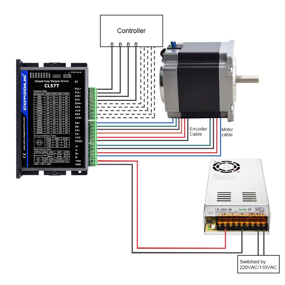
3. Wiring Diagrams
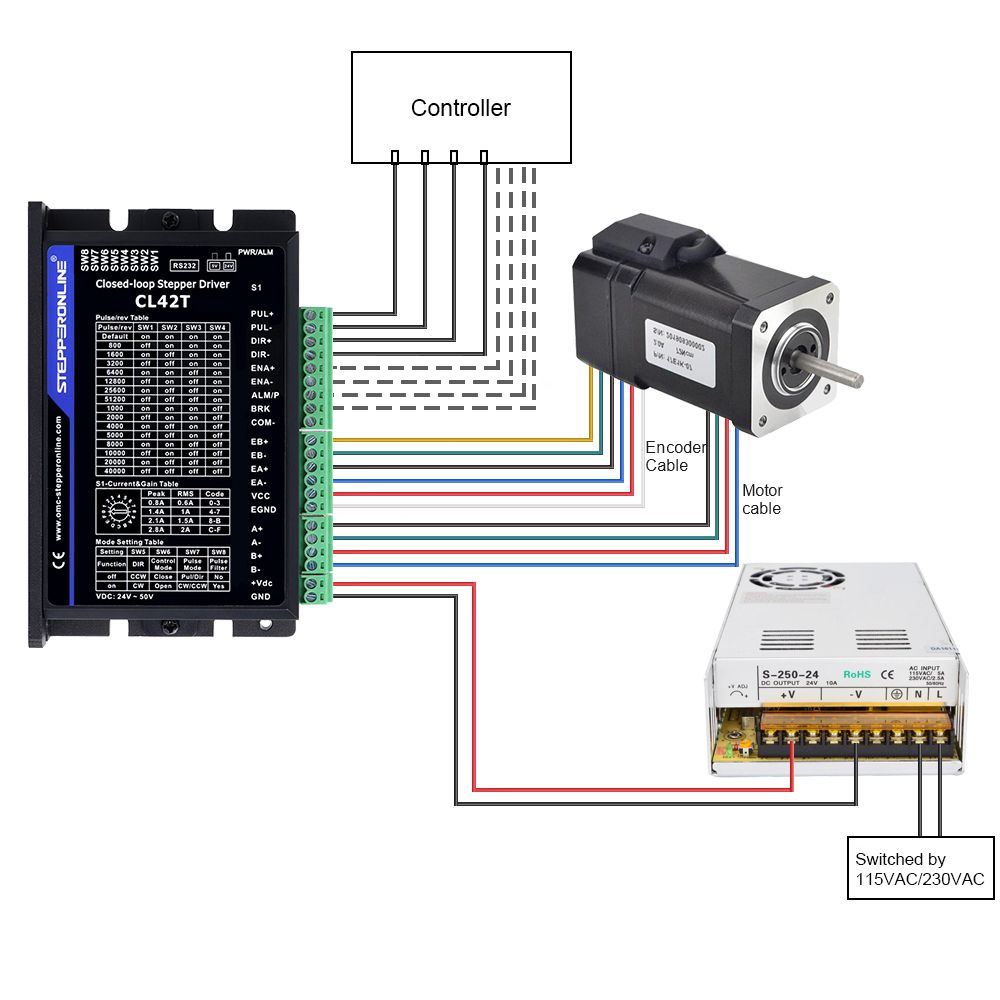
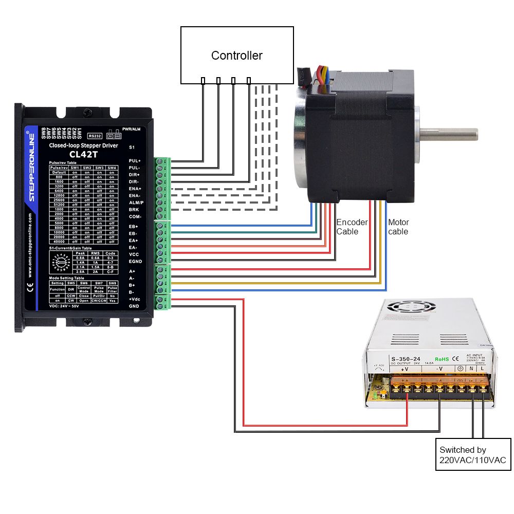
3.1 The CL42T is recommended for NEMA 17 or smaller closed-loop stepper motors, with a recommended supply voltage of 24 V DC.
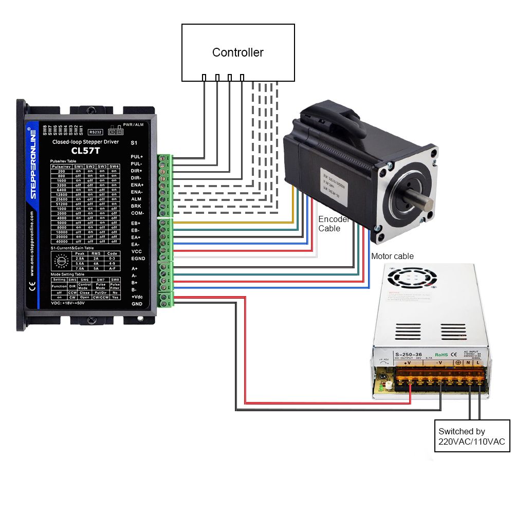
3.2 The CL57T is recommended for NEMA 23 or NEMA 24 closed-loop stepper motors, with a recommended supply voltage of 24–48 V DC.
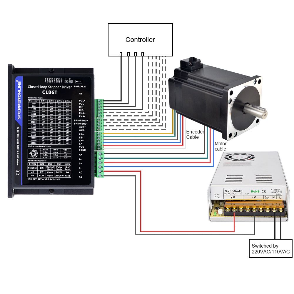
3.3 The CL86T is recommended for NEMA 34 closed-loop stepper motors, with a recommended supply voltage of 36–60 V DC.
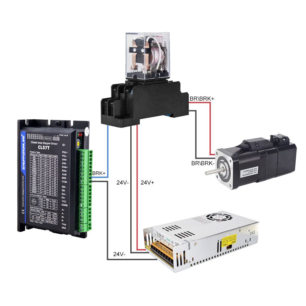
4. Wiring Diagram for CL57T with Brake
5. Wiring Diagrams for Magnetic Encoder Closed-Loop Stepper Motors
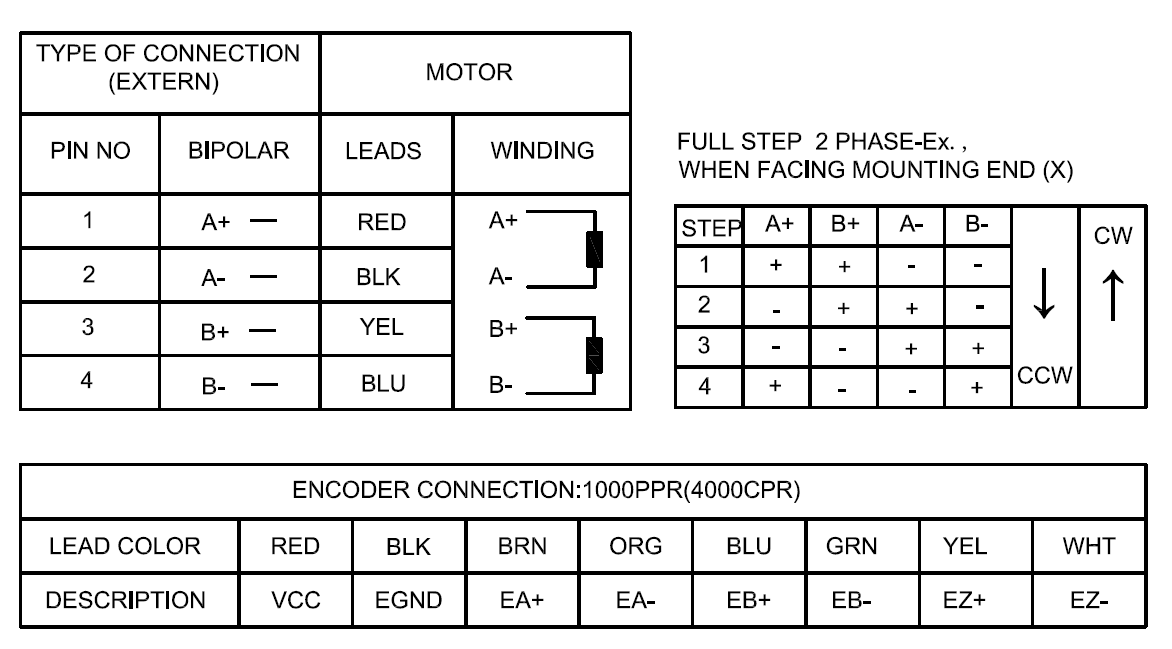
Magnetic encoder closed-loop stepper motors do not have an extension cable. Refer to the wiring diagram printed on the motor label for the pinout.
Please refer to the wiring diagrams below for the pinout and connection details of the 17HS15-1504-ME1K and 17HS19-2004-ME1K motors:
5.1 17HS15-1504-ME1K
5.2 23HS22-2804-ME1K