This article describes how to wire the alarm (ALM) signal on StepperOnline brushless motor drivers.
1. Alarm Signal Characteristics
Output Type: NPN Open-Collector Output (Sinking Output)
Signal Level:
- Alarm State (ALM ON): The output transistor conducts, pulling the ALM pin to GND (≈ 0 V, logic LOW).
- Normal State (ALM OFF): The output is high-impedance (floating). An external pull-up resistor or the relay coil pulls the ALM pin HIGH (to the relay supply voltage, e.g., 5 V).
2. Wiring Diagram: 5 VDC Relay Connection
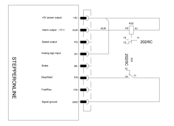
When the brushless driver operates normally, relay K02 remains de-energized. When the driver detects an alarm condition, relay K02 is energized.
3. Precautions
3.1 Relay Polarity Must Be Correct
Connect the relay between the power supply (+V) and the ALM output so that current flows from +V through the relay coil into the ALM pin and then to GND internally (current path: +V → Relay Coil → ALM → GND).
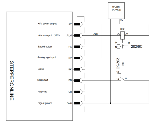
3.2 Match the Relay Rated Voltage
- 5 VDC relay: Connect the positive terminal to the +5 V supply and the negative terminal to the ALM pin (as shown in the diagram above).
- 12 VDC or 24 VDC relay: A separate 12 VDC or 24 VDC power supply is required. See the wiring diagram below.
3.3 Signal Anti-Interference Design
- Cable lengths > 1 m: Use twisted-pair shielded cable. Ground the shield to the driver's GND at one end only.
- High-noise environments:
- Connect a 10 kΩ pull-down resistor between ALM_OUT and GND to prevent the floating input from triggering false alarms due to electrostatic discharge. Note: If an external pull-up resistor is already present, ensure the pull-up value is significantly lower than 10 kΩ to avoid forming a voltage divider that degrades the HIGH-level signal.
- Connect a 0.1 µF capacitor across the relay coil to suppress back-EMF (inductive voltage spikes).
4. Summary
The alarm signal (ALM) on StepperOnline brushless motor drivers is an NPN open-collector output (active LOW). It requires an external pull-up—typically provided by the relay coil—to maintain a HIGH level in the normal (non-alarm) state.
When driving a relay:
- Always connect the relay coil between the power supply (+V) and the ALM pin.
- Ensure the relay coil voltage matches the power supply. Use an independent power supply for non-5 V relays.
- For long cable runs or noisy environments, follow the shielding and RC anti-interference measures described above to ensure signal reliability.