- What Are Inertia and Inertia Ratio?
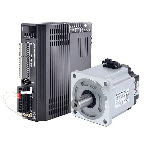
The rotor moment of inertia (often simply called "rotor inertia") is a measure of the motor rotor's resistance to changes in rotational speed. It is a critical parameter that directly affects the motor's acceleration and deceleration performance. Therefore, when selecting a servo motor, it is essential to consider the motor's rotor inertia, as it directly impacts performance and operational stability. You can find the rotor moment of inertia value in the motor's specification sheet. STEPPERONLINE offers servo motors in various inertia ratings. Please refer to the specific motor's datasheet for its rotor moment of inertia value.
The load inertia ratio is the ratio of the total load inertia (reflected to the motor shaft) to the motor's own rotor moment of inertia. The load moment of inertia represents the inertia of the mechanical load driven by the motor. The greater the load moment of inertia, the poorer the system's responsiveness. If the load inertia is excessively high, it may cause unstable motion and vibration. The permissible load inertia ratio is limited by the servo motor's allowable load inertia specification and may vary depending on the operating conditions of the servo system.
When the motor is operated beyond the allowable load moment of inertia, an overvoltage alarm may occur during deceleration. Additionally, if the regenerative energy exceeds the capacity of the built-in braking resistor, a regenerative overvoltage alarm may occur. If such an alarm is triggered, you can take any of the following actions:
● Reduce the torque limit value ● Increase the deceleration time (reduce the deceleration rate) ● Reduce the maximum speed ● If the alarm persists after applying the above measures, an external braking resistor is required
- How to Choose the Appropriate Inertia Ratio?
There are two methods for determining the load inertia ratio:
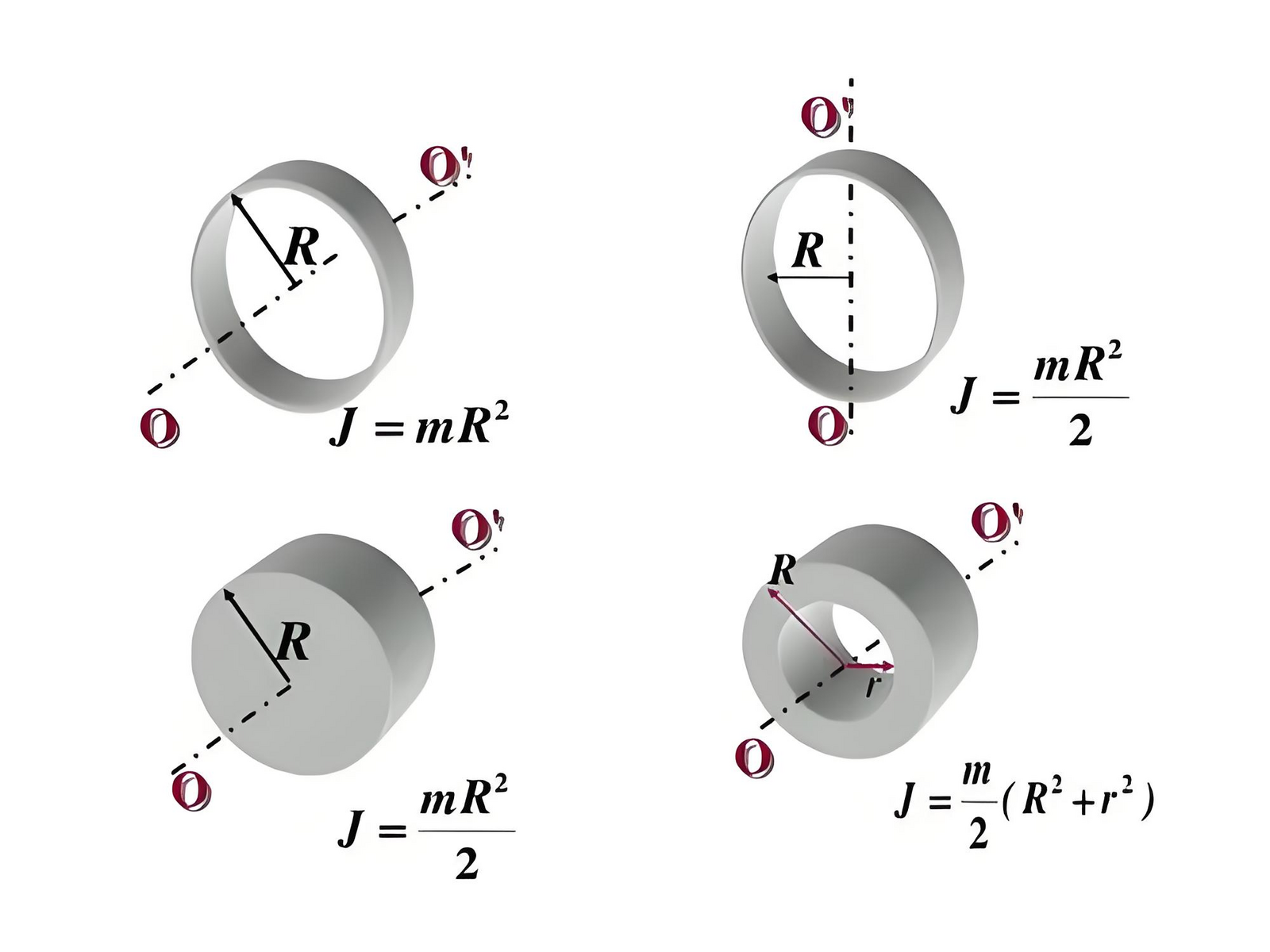
● Manual calculation: This involves calculating the mass and geometry of each component in the system to derive the total load inertia. However, this method is labor-intensive, and for complex servo systems, it can be difficult to calculate the correct load inertia ratio accurately.
● Automatic inertia identification: The most commonly used method is automatic identification via the inertia auto-tuning function of the servo drive. During the identification process, the drive commands the servo motor to rotate in the forward and reverse directions several times to determine the appropriate load inertia ratio. All servo drives currently sold by STEPPERONLINE support this function.
Please note that the inertia identification procedures vary across different series of STEPPERONLINE servo drives. Before performing the operation, carefully read the detailed inertia identification instructions in the drive's user manual.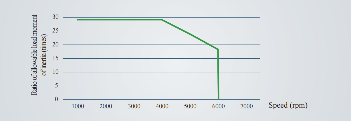
Typically, the recommended maximum load inertia ratio is around 30:1 (as shown in the figure). If your system load exceeds this upper limit, it is recommended that you add a reduction gearbox to lower the load inertia reflected to the motor shaft. The load inertia reflected to the motor shaft is reduced by the square of the gear ratio. At the same time, considering the impact of the gearbox on motor speed, it is recommended to select a gearbox with a gear ratio of 5:1 or 10:1, which can achieve a suitable inertia ratio without excessively reducing the output speed.