The enable signal (ENA) on a stepper driver controls the driver's operating state. When the ENA signal is active (low level / enabled), the driver receives and responds to pulse signals, driving the stepper motor to rotate. When the ENA signal is inactive (high level / disabled), the driver ignores pulse signals and the motor does not rotate.
The main functions of the enable signal (ENA) are:
- Motor protection: Disabling the driver when the motor does not need to run helps protect the motor and reduces mechanical wear.
- Energy savings: Disabling the driver effectively reduces the motor's power consumption when it is idle.
1. How to Connect ENA
The ENA signal typically uses two wires: ENA+ and ENA-. ENA+ is usually connected to a 5 V (or other appropriate voltage) output on the controller, and ENA- is connected to the controller's enable signal output. When the controller's enable output is at a low level, the stepper driver is enabled and responds to pulse signals; when the enable output is at a high level, the driver is disabled and does not respond to pulse signals.
Note: The DM320T and DM332T drivers do not have a dedicated ENA- terminal. Instead, the controller's enable signal output should be connected to the OPTO common port. In this configuration, OPTO serves as ENA+.
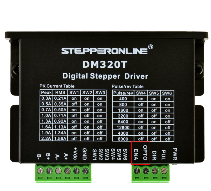
2. Applications
The ENA signal is essential in many applications. For example, it is widely used in robots, CNC machines, and automation equipment that require precise control of motor rotation. By controlling the ENA signal, the start and stop behavior of the stepper motor can be managed accurately, enabling precise control of equipment movement.
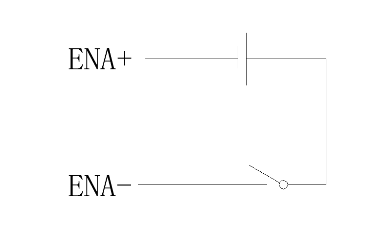
Example — Manual alarm-clear function for closed-loop drives: Connect the ENA+ and ENA- terminals to a 5 V / 24 V power supply through a switch to form a closed circuit. This method clears position-following errors only; it does not clear other alarm types (see figure below). Note: This wiring method applies only to closed-loop stepper drivers.
Please note that different stepper drivers may have different ENA signal level requirements and wiring methods. Always refer to the specific driver manual for your model before wiring.