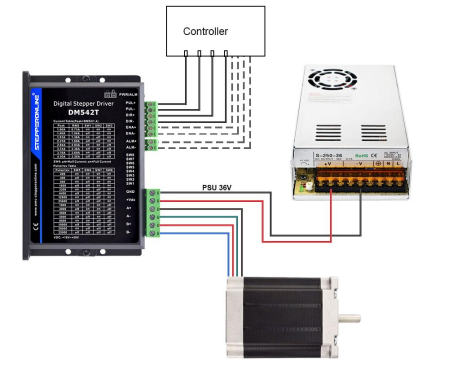
This article provides wiring guidance for open-loop stepper motors. Refer to the diagram below for your motor's specific wiring sequence.
If the motor's wiring sequence is A+ (Black), A- (Green), B+ (Red), B- (Blue), use the following wiring diagram as a reference:
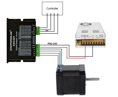
The OPTO pin on the DM320T is the common anode for the optically isolated inputs. Connect it to the controller's VCC (5V). If the controller outputs a higher voltage (e.g., 12V or 24V), a current-limiting resistor must be added in series to prevent damage to the optocoupler.