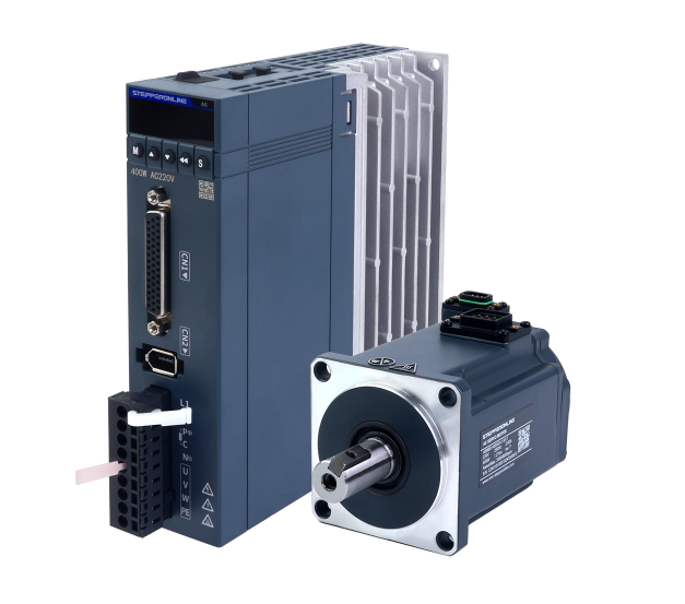
In servo system applications, the holding brake is a critical safety component that ensures rapid stopping and position holding during power loss or emergency conditions. Proper brake wiring not only guarantees safe equipment operation but also prevents mechanical damage or personal injury caused by incorrect operation. This document details the wiring procedures and precautions for A6 series servo motor brakes and applies to all standard 24V DC brakes used in A6 series servo motors.
Below are two wiring methods for the A6-RS, A6-EC, and A6-PN series brakes. Choose the method that best suits your application.
Method 1: Using a Relay
- Preparations:
-
An A6 servo motor properly connected to the drive.
-
A 24V DC power supply (rated for at least the brake coil power consumption, typically ~7W).
-
A relay with at least one NO (Normally Open) and one NC (Normally Closed) contact.
-
Wires (AWG24 or thicker).
-
A 220V AC power supply for the servo drive.
- Wiring for A6-RS Series:
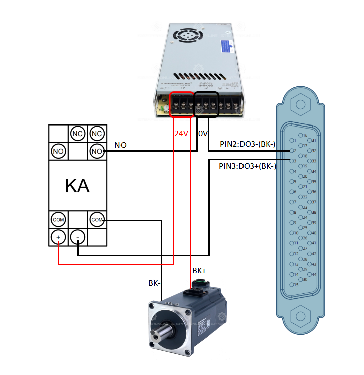
Refer to the diagram above. Six wires are required:
-
Connect 24V+ from the power supply to one of the relay coil terminals (e.g., A1 or +).
-
Connect 24V+ to the motor brake's BK+ terminal.
-
Connect 0V (GND) to the relay's NO contact terminal.
-
Connect 0V (GND) to CN1-PIN2 (DO3−) on the drive. Note: DO3 is the default digital output assigned to brake control. If you reassign brake control to DO1 or DO2, connect to the corresponding pins instead.
-
Connect the relay's COM contact terminal to the motor brake's BK− terminal.
-
Connect the other relay coil terminal (e.g., A2 or −) to CN1-PIN3 (DO3+).
- Wiring for A6-EC/A6-PN Series:
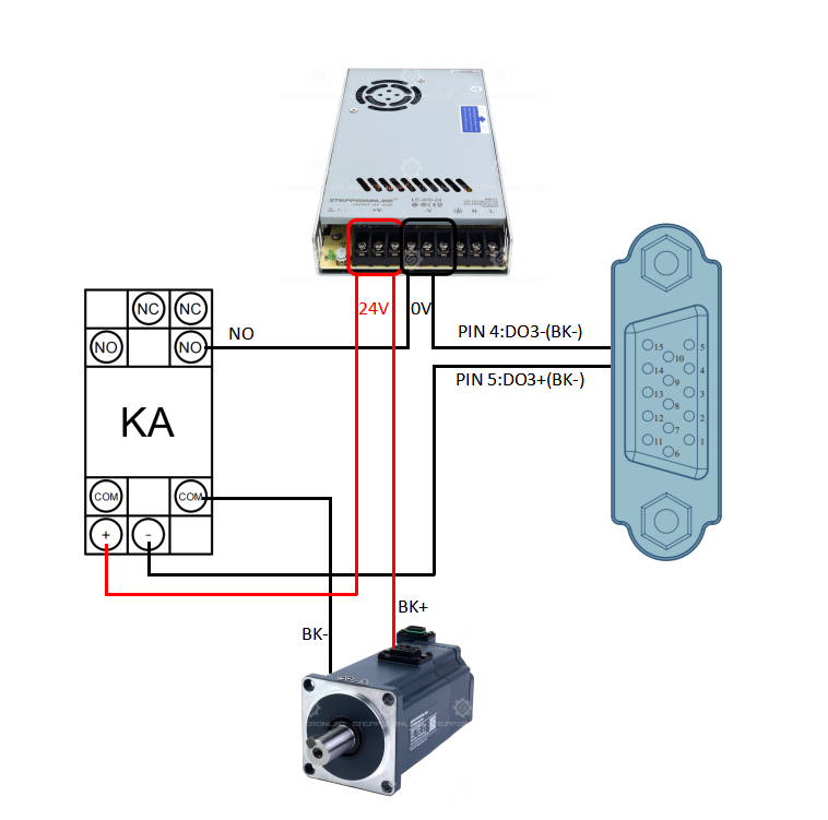
The wiring method is similar:
-
Connect 24V+ to one of the relay coil terminals (e.g., A1 or +).
-
Connect 24V+ to BK+.
-
Connect 0V (GND) to the relay's NO contact terminal.
-
Connect 0V (GND) to CN1-PIN4 (DO3−). Note: DO3 is the default digital output assigned to brake control. If you reassign brake control to DO1 or DO2, connect to the corresponding pins instead.
-
Connect the relay's COM contact terminal to BK−.
-
Connect the other relay coil terminal (e.g., A2 or −) to CN1-PIN5 (DO3+).
The relay acts as a switch, enabling real-time control of the brake through either the drive or an external controller. When the motor is enabled, you will first hear a click (the relay contact closes and the power indicator lights up), followed by a second click (the brake releases). In summary: enabling the motor releases the brake; disabling the motor engages the brake. (Note: The motor shaft remains electromagnetically locked when enabled and cannot be rotated manually.)
To release the brake for testing without enabling the motor, use one of the following methods:
One method is to modify the DO3 function logic. Refer to the drive manual for a full description of DO3 functions:
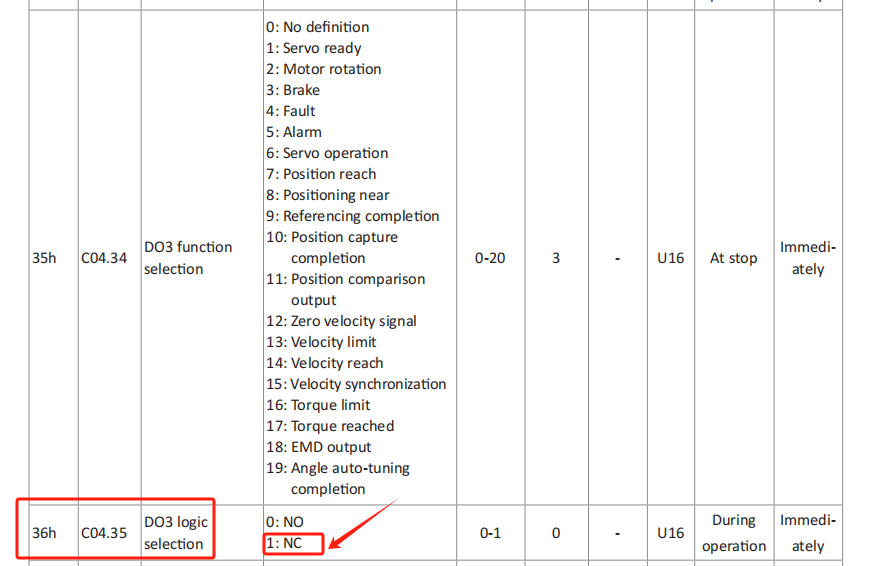
The factory default sets the DO3 logic to NO. You can use the drive's front panel or configuration software to change the DO3 function logic to NC. After this change, you will hear two clicks as the relay activates and the brake releases. Because the motor is not enabled at this point, you can rotate the motor shaft freely by hand. After testing, it is strongly recommended that you reset the DO3 function logic back to NO. Otherwise, when the motor is enabled, the DO3 output will turn off (due to the NC logic), de-energizing the relay and causing the brake to engage. If a motion command is issued while the brake is engaged, the motor will attempt to rotate against the locked brake, which can cause severe damage to the brake mechanism.
Method 2: Direct 24V Power Supply Wiring (Without Relay)
- Preparations:
-
An A6 servo motor properly connected to the drive.
-
A 24V DC power supply.
-
A 220V AC power supply for the servo drive.
- Brake Wiring for A6-RS/A6-EC/A6-PN Series:
As shown in the diagram below, because no relay is used and the drive's digital outputs are not involved, the wiring method is identical for all three A6 series models. Simply connect the motor brake wires BK+ and BK− directly to the 24V DC power supply.
When power is applied, the brake releases.
When power is removed, the brake engages.
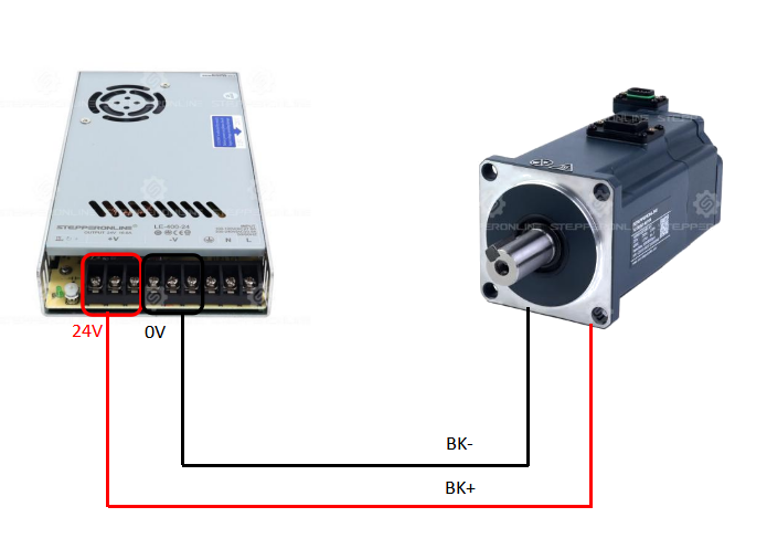
The advantage of this method is its simple wiring. Brake operation is controlled directly by switching the power supply on or off, which also provides a convenient way to verify brake functionality. However, because this method uses a direct power supply connection without a control switch, it is not suitable for complex applications that require independent brake control after the motor is enabled.
Important Notes
The motor holding brake is designed exclusively for holding a stationary load (maintaining load position after the motor has stopped). Never use the holding brake to decelerate a moving load, as this may cause severe damage to both the brake and the motor.