The "position error" alarm is a common fault in closed-loop stepper systems. It occurs when the driver detects that the difference between the motor's actual position and the commanded position from the control system exceeds the configured allowable range (the position error threshold).
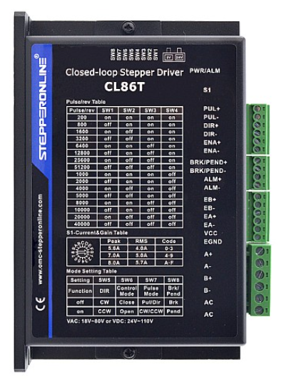
I. Main Causes
- Mechanical Structure and Load Issues (Most Common)
- Mechanism jam or excessive resistance
- Overload or excessive inertia
- Damaged mechanical components
- Electrical Connection and Component Issues
- Incorrect wiring or poor contact
- Damaged motor
- Damaged encoder
- Internal driver fault
- Driver Parameter Settings
- Position error threshold set too small
II. Troubleshooting Steps
Step 1: Power-Off Mechanical and Visual Inspection
Safety Notice: Ensure the drive is fully powered off and that DC bus capacitors are discharged before performing any mechanical inspection or manual rotation.
- Test without load: Disconnect the motor from the load mechanism.
- If the alarm stops during no-load operation, the problem is most likely on the mechanical load side.
- Check for: jamming mechanisms, poor lubrication, excessive load weight, and overly tight or loose timing belts.
- Manual rotation check: With the power off, try rotating the motor shaft manually.
- Normal: The shaft should feel smooth with uniform resistance.
- Abnormal: Obvious catching, roughness, or extreme resistance indicates mechanical failure.
Step 2: Power-On Static and Parameter Check
- Verify wiring: Ensure motor wires (A+, A-, B+, B-), encoder cables, and power cables (Vdc, GND) are correctly and securely connected per the manual.
- Position error threshold: Check the current setting. If vibration is present, you may temporarily increase this value to prevent nuisance alarms. Warning: This does not fix the underlying issue. A large position error threshold may mask real mechanical faults. Always investigate and resolve the root cause.
Step 3: Measurement Methods
- Pulse signal measurement: Use an oscilloscope to check the pulse (PUL) and direction (DIR) signals from the controller.
- Verify clean waveforms, correct frequency, and absence of noise.
- Encoder feedback measurement (if supported): For closed-loop steppers, use an oscilloscope to verify proper encoder signal output.
Step 4: Cross-Testing
- Replace motor: Test with a known-good motor of the same model.
- Replace driver: Test with a known-good driver of the same model.
- Replace cables: Replace encoder cables if possible. If you are unsure whether the cables are faulty or how to replace them, contact technical support.
Summary
Through systematic troubleshooting, most root causes of position error alarms can be identified and resolved. Always start with the mechanical load and basic wiring—the most common causes—for efficient problem resolution.