Pulse Signal Control (Position Control Mode)
This is the most common and intuitive method for servo control. The controller (such as a PLC or motion control card) controls the motor by sending a train of pulses. Our A6-RS/T6-RS and DSY-RS servo motors support this control mode.
Working Principle Diagram:
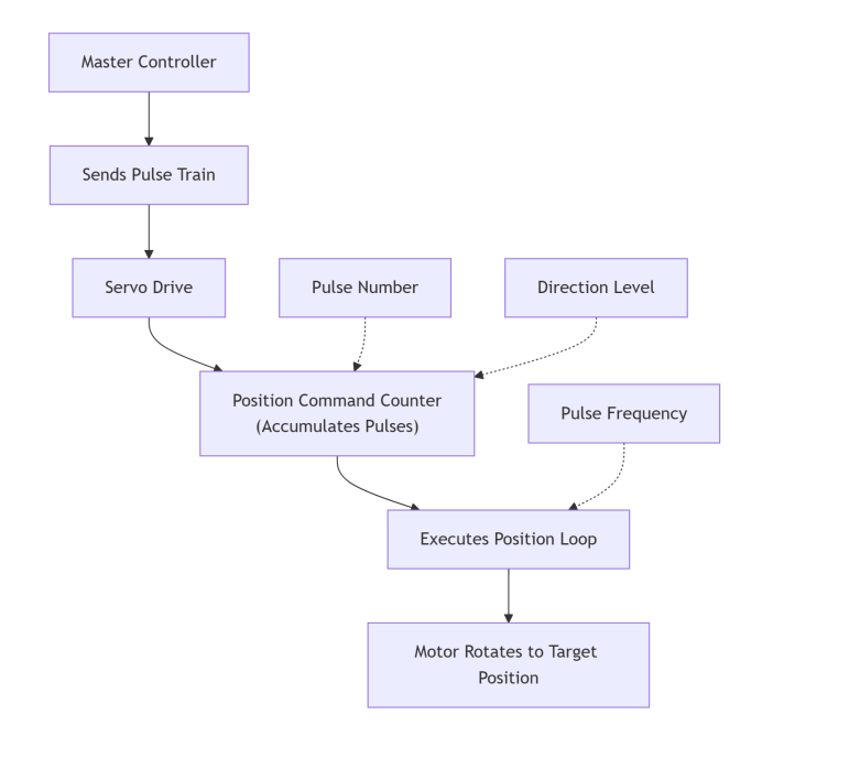
1.1. Pulse Quantity: The drive has a built-in position command counter. Each pulse received increments (or decrements) the counter by one. For example, if the drive parameter is set to "10,000 pulses per revolution," sending 10,000 pulses will cause the motor to rotate exactly 360 degrees.
1.2. Pulse Frequency: The frequency determines the speed at which the motor executes the movement. A higher frequency results in a faster motor speed.
1.3. Direction Signal: A high or low level signal determines whether the pulse counter counts up or down, thereby controlling the motor's forward or reverse rotation.
1.4. Characteristics: In this mode, the controller has real-time control over every incremental movement of the motor. If the pulse transmission stops, the motor will stop upon reaching the target position. This is a pulse-by-pulse tracking control method.
PWM Signal Control (Speed/Torque Control Mode)
In this application, the PWM signal is not used directly as a pulse command, but is instead filtered into an analog voltage to serve as a speed or torque reference. Our A6-RS servo motors also support PWM signal control.
Working Principle Diagram:
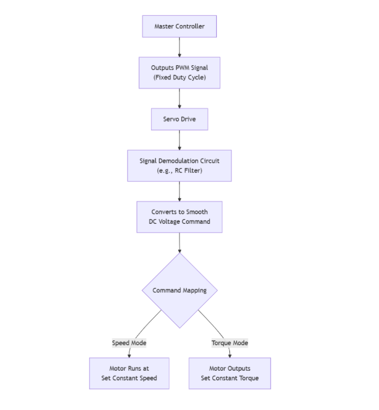
2.1. Signal Filtering: The servo drive contains an internal hardware circuit (such as an RC low-pass filter) that converts the incoming PWM square wave into a smooth DC voltage. Example (actual mapping depends on drive parameters): A 50% duty cycle might correspond to 0V, a 10% duty cycle to -5V, and a 90% duty cycle to +5V.
2.2. Command Mapping: The resulting DC voltage value serves as the speed or torque command.
- Speed Mode: -10V to +10V corresponds to the motor's maximum reverse speed to maximum forward speed.
- Torque Mode: -10V to +10V corresponds to the motor's maximum reverse torque to maximum forward torque.
2.3. Characteristics: In this mode, the controller sets a target value. For instance, setting a fixed duty cycle causes the motor to rotate at a corresponding constant speed without requiring the controller to continuously send signals. This is a setpoint-based control method.
Summary and Selection Advice
| Requirements | Recommended Control Method |
|---|---|
| Need precise control of position and movement trajectory (e.g., point-to-point, interpolated motion) | Pulse Signal (Position Mode) |
| Need to maintain constant speed (e.g., conveyor belts, mixers) | PWM Signal (Speed Mode) or Analog Voltage |
| Need to maintain constant torque (e.g., screw tightening, winding) | PWM Signal (Torque Mode) or Analog Voltage |