⚠️ Safety Warning: Perform all wiring operations only with the power completely disconnected. During live testing, ensure the motor shaft is unloaded to prevent unintended startup.
When a brushless motor runs smoothly in one direction but exhibits jerking, weakness, or fails to run in the opposite direction, focus troubleshooting on the following three common causes. Please check them in order.
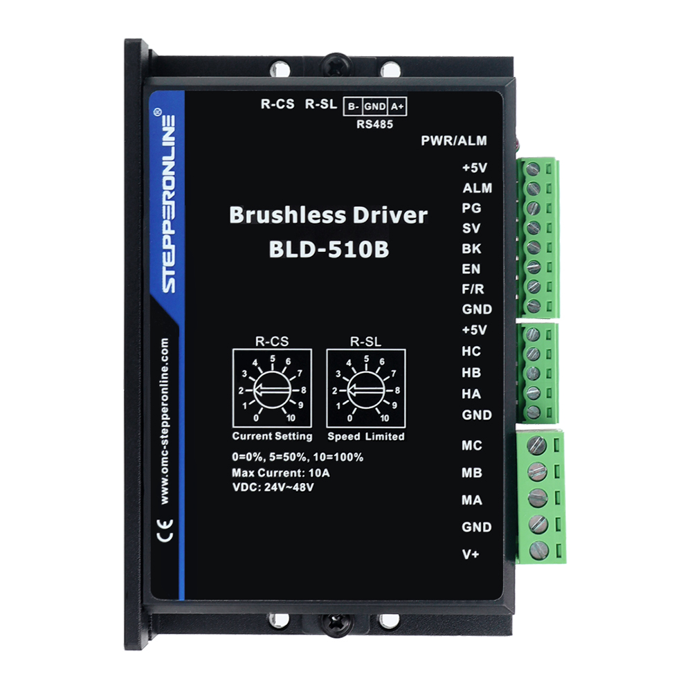
1. Check the Hall Signals (For Hall Effect Sensor Motors)
1.1. Symptom: Normal forward rotation, but severe jerking, abnormal noise, or complete locking during reverse rotation.
1.2. Possible Cause: A damaged Hall effect sensor inside the motor or poor contact in one of the signal wires, preventing the controller from identifying the correct commutation position.
1.3. Solution:
- Observation Method: Slowly rotate the motor shaft manually. Use a multimeter to measure the voltage between each of the three Hall signal wires (not the red/black power wires) and ground. Under normal conditions, the voltage on each signal line should fluctuate regularly between 0 V and 5 V (or 3.3 V). If one line's voltage remains constant, the corresponding Hall effect sensor is likely faulty.
- Replacement Method: If possible, substitute the motor with a known-good unit of the same model. If the problem disappears, the Hall effect sensor assembly in the original motor is likely faulty and requires repair or replacement.
2. Check the Speed Control Signal
2.1. Symptom: The motor consistently rotates in a single direction regardless of the forward/reverse command.
2.2. Possible Cause: If using an analog voltage (e.g., 0–5 V) for speed control, the signal wire may be subject to electrical interference, or a zero offset may be present (meaning 0 V no longer corresponds to zero speed).
2.3. Solution:
- Measure Zero Offset: When the controller sends a "stop" command, use a multimeter to measure the voltage between the speed control signal wire and ground. The ideal value is 0 V. If a small voltage (e.g., above 0.1 V) is detected, a zero offset exists.
- Check Wiring: Ensure signal wires are properly shielded, routed away from power cables, and that all terminals are tight and secure.
3. Adjust Hall Wire Sequence
⚠️ Reminder: Ensure the power is completely disconnected before making any wiring changes in this section.
3.1. Symptom: The motor rotates in only one direction.
3.2. Root Cause: The angular relationship (phase sequence) between the Hall effect sensors and the three-phase windings may not match the controller's expected commutation logic. This typically occurs when using a different or third-party driver, or after rewiring.
3.3. Solution:
- Secure the Power Wires: Firmly connect the three main power wires (U/V/W) to the motor and leave them unchanged throughout the test.
- Label Hall Wires: Label the motor's three Hall signal wires (typically yellow, green, blue, etc.) as A, B, and C.
- Six Tests: Connect these three wires to the driver's Hall signal ports in all six possible sequence combinations. After each connection, power on and test the motor at low speed in both forward and reverse directions.
- Find the Optimal Combination: Compare the results of all six tests to identify the single wiring sequence that produces equally smooth, quiet, and powerful operation in both directions. This is the correct Hall wire sequence for the current power wire configuration. Permanently secure this wiring.