There are several common methods for identifying the wiring sequence of a hybrid two-phase stepper motor.
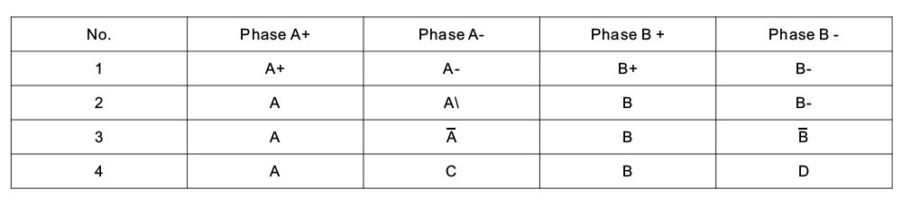
4-Wire Stepper Motor Example:
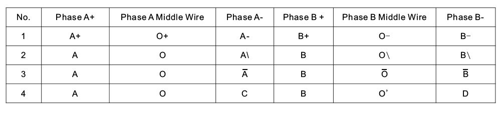
6-Wire Stepper Motor Example:
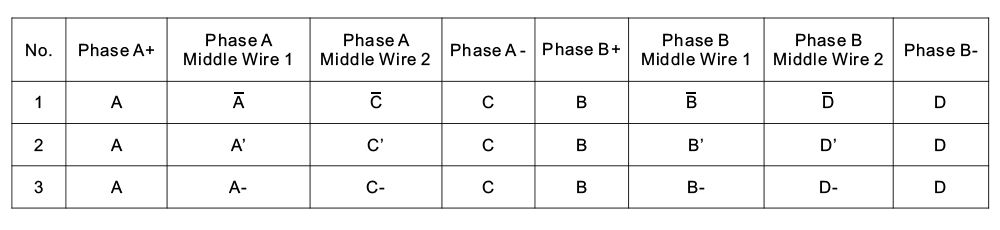
8-Wire Stepper Motor Example:
The motor output terminals on a stepper driver are typically labeled A+, A-, B+, and B- (see the figure below). A+ and A- correspond to one phase (coil), while B+ and B- correspond to the other phase.
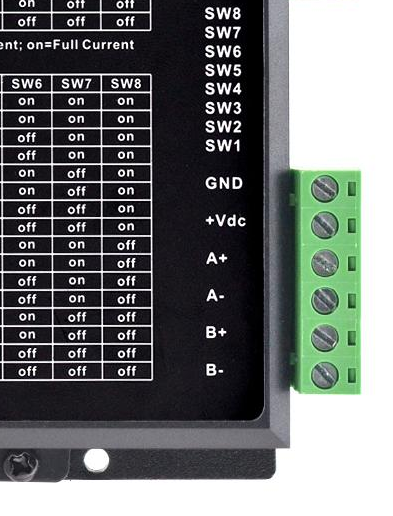
Note that some driver boards use different terminal markings.
For example:
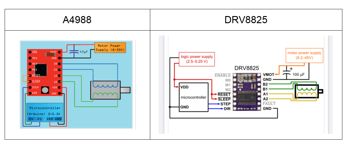
- A4988: Terminals are labeled 2B, 2A, 1A, and 1B. 2B and 2A form one phase; 1A and 1B form the other phase.
- DRV8825: Terminals are labeled B2, B1, A1, and A2. B1 and B2 form one phase; A1 and A2 form the other phase.
For specific wiring instructions, always refer to your driver's manual. Below are the wiring diagrams for the A4988 and DRV8825.